Model 30-90Screw Diameter φ30-90 mmL/D Ratio 26:1/25:1Extrusion Output 25-250 kg/hrMain Motor 18-63 KWOutlet Diameter 0.2-35 mmSpeed 10-600 m/minApplication Sensor signal & other electronic wires
Sensor Signal Cable Extrusion Line
In simple terms, a sensor signal cable is the "nerve" or "blood vessel" connecting a sensor to a controller (such as a PLC, data acquisition card, or instrument). Its core task is to accurately, reliably, and without distortion transmit the weak electrical signal converted from the physical quantity (e.g., temperature, pressure, displacement) perceived by the sensor to the processing unit.
Core Functions and Importance
Many people underestimate the importance of signal cables, considering them just ordinary wires. However, the quality of the signal cable directly determines the performance and stability of the entire measurement system.
Signal Transmission Quality: High-quality signal cables ensure signal integrity, reducing attenuation and distortion.
Anti-Interference Capability: Industrial environments are filled with electromagnetic interference. Signal cables are the first line of defense against interference, preventing noise from "contaminating" the useful signal.
System Stability and Safety: Poor-quality or incorrectly selected signal cables can cause signal fluctuation, data loss, or even damage to downstream equipment. Good shielding and insulation protect equipment and personnel safety.
Long-Distance Transmission: Signals attenuate over long distances. Suitable cables can extend the effective transmission range.
Key Structure and Characteristics
A qualified sensor signal cable typically consists of the following parts from the inside out:
Conductor
Material: Copper is typically used for its good conductivity. Tin-plated copper is used for higher requirements to enhance corrosion resistance; silver is used in special applications for high-frequency performance.
Structure: Divided into solid core (hard wire) and stranded (soft wire). Stranded wire is more flexible and suitable for moving applications or scenarios requiring frequent bending.
Insulation Layer
Function: Prevents short circuits between conductors and provides basic insulation protection.
Material: PVC (Polyvinyl Chloride), PE (Polyethylene), PP (Polypropylene), Teflon (PTFE), etc. Different materials vary in temperature resistance, chemical resistance, flexibility, etc. For example, Teflon offers excellent high-temperature resistance.
Shielding Layer
Function: Defends against external electromagnetic interference and prevents internal signals from radiating out and interfering with other equipment. It is the core of the cable's anti-interference capability.
Types:
Braid Shield: Made from woven fine copper wires. Offers good flexibility and strong low-frequency interference resistance.
Foil Shield: A layer of aluminum foil + a drain wire. Offers high coverage (close to 100%) and strong high-frequency interference resistance, but poorer flexibility.
Combination Shield: Foil + braid. Combines the advantages of both, providing the most comprehensive protection. Common in highly demanding applications.
Sheath (Jacket)
Function: Protects the internal structure from mechanical damage (such as abrasion, crushing), chemical corrosion (oil, water, acids, alkalis), UV light, and other environmental factors.
Material: Typically PVC, PUR (Polyurethane), TPE (Thermoplastic Elastomer), etc. PUR is very wear-resistant, oil-resistant, and flexible, often used in drag chain cables.
Other Elements
Drain Wire: In contact with the shielding layer, used to guide the noise current induced in the shield to ground.
Filler: Helps the cable maintain a round shape and increases mechanical strength.
Main Types and Selection
Based on the type of signal output by the sensor, signal cables mainly include the following:
Analog Signal CablesCharacteristics: Transmit continuously varying voltage or current signals, such as 0-10V, 4-20mA. They are highly susceptible to interference and require the highest level of shielding.
Common Structure: Typically use a twisted pair + shield structure. Twisting causes noise induced on the two wires to be equal in magnitude and opposite in phase, thus canceling each other out, greatly improving common-mode noise rejection.
Application: Temperature sensors (thermocouples, RTDs), pressure transmitters, flow meters, etc.
Digital/Bus Signal CablesCharacteristics: Transmit digital pulses or signals following specific communication protocols (e.g., RS485, CANopen, Profibus, EtherCAT).
Common Structure: Also often use twisted pair(s) + shielding, but have strict requirements for characteristic impedance, capacitance, etc., necessitating the use of dedicated cables.
Application: Incremental encoders, absolute encoders, IO-Link devices, various fieldbus devices.
Power CablesCharacteristics: Solely provide operating power to the sensor. Generally require less shielding, but require a sufficient conductor cross-section to reduce voltage drop.
Note: Many sensor cables integrate power and signal lines into a single cable, called a "composite cable" or "hybrid cable".
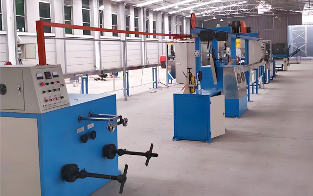
Sensor Signal Cable Extrusion Line
An extrusion production line for sensor signal cables is a complete set of industrial equipment used to manufacture the insulation layer and sheath of sensor signal cables. It is an automated system that heats and plasticizes plastic pellets (such as PVC, PE, PUR, etc.) and then continuously and uniformly coats them onto the conductor (e.g., copper wire) or cable core, forming the insulation layer or sheath layer.
Production Objects: Specifically used for manufacturing sensor signal cables that require extremely high precision and consistency, such as:
Twisted-pair shielded cables (for analog signal transmission)
Encoder cables
Servo motor cables
Fieldbus cables (e.g., PROFIBUS, CANopen, etc.)
Core Components
A complete extrusion production line typically consists of the following major sections:
Pay-off SystemFunction: Used to pay off the conductor or cable core that needs to be coated.
Types:Passive Pay-off: Relies on the pulling force from the downstream caterpillar haul-off to rotate the reel.
Active Pay-off: Equipped with a motor drive capable of providing stable tension control. This is a key configuration for sensor cable production. Constant tension prevents conductor stretching or internal stress generation, ensuring stable electrical performance.
Preheating System (Optional but Important)Function: Preheats the conductor before it enters the die head.
Purpose:Removes moisture from the conductor surface.
Promotes tighter adhesion between the plastic melt and the conductor, reducing internal stress and bubbles, thereby improving insulation quality.
Extruder System - Core ComponentFunction: Heats, plasticizes, and homogenizes solid plastic pellets through heating and shear, then steadily conveys the melt to the die head.
Composition:Hopper: Stores and feeds plastic pellets.
Screw and Barrel: The core working components. The screw rotates within the barrel, conveying, compressing, melting, and mixing the plastic. Different screw designs are used based on plastic characteristics (e.g., for PVC or PUR).
Heating/Cooling System: Precisely controls the temperature of each zone via electric heating bands and air/water cooling systems.
Drive Motor: Provides power for the screw rotation, requiring stable and adjustable speed.
Die Head and ToolingFunction: Guides the molten plastic and shapes it precisely and concentrically around the conductor.
Types:Pressure Die: Mainly used for extruding the sheath layer, providing an overall jacket over the cable core.
Semi-Pressure Die/Tubing Die: Used for insulation extrusion, capable of achieving high concentricity. This is the preferred choice for sensor cable insulation production.
Requirement: High-precision machining to ensure uniform plastic flow and no dead spots.
Cooling SystemFunction: Rapidly cools and sets the plastic-coated cable.
Type: Segmented cooling water trough. Water temperature needs precise control, as cooling too fast or too slow affects crystallinity and surface quality.
Online Diameter Gauge - Key Quality Control EquipmentFunction: Measures the cable's outer diameter in real-time, non-contact, and displays it digitally or as a waveform graph.
Importance: It is the basis for achieving closed-loop control. It instantly detects diameter variations (e.g., eccentricity, oversize/undersize) and provides feedback to the control system for adjustment, ensuring micron-level product tolerances.
Spark Tester (Primarily used for insulated wire production)Function: Performs online detection of insulation layer defects such as pinholes or scratches. It applies a high voltage; any defect causes a spark discharge which is recorded.
Caterpillar Haul-offFunction: Provides stable pulling force to draw the cable through the entire production line at a constant speed.
Requirement: Speed must be extremely stable and jerk-free. Dual-wheel or belt-type caterpillar haul-offs are typically used to prevent slipping.
Take-up SystemFunction: Winds the finished cable neatly onto a reel.
Types:
Passive Take-up: Driven by the haul-off.
Active Take-up: Equipped with a motor and tension control system, enabling constant tension winding. This ensures neat, consistent reel winding and avoids cable damage.
Control SystemFunction: The "brain" of the entire production line.
Composition: Typically uses a PLC (Programmable Logic Controller) + Touch Screen HMI (Human-Machine Interface).
Control Parameters: Precisely controls zone temperatures, screw speed, synchronization between haul-off and take-up speeds, tension, etc. Advanced systems can integrate the diameter gauge for automatic feedback control.
Production Process Flow
Typical production process flow:
Pay-off → Preheating → Extrusion → Shaping → Cooling → Diameter Measurement/Spark Testing → Printing → Haul-off → Take-up.
Sensor Signal Cable Extrusion Line Datasheet
| Model |
30 |
40 |
50 |
60 |
70 |
80 |
90 |
| Screw Diameter (mm) |
φ30 |
φ40 |
φ50 |
φ60 |
φ70 |
φ80 |
φ90 |
| Screw L/D Ratio |
25:1 |
25:1 |
26:1 |
26:1 |
26:1 |
26:1 |
26:1 |
| Extrusion Amount (kg/hr) |
25 |
40 |
70 |
100 |
140 |
200 |
250 |
| Outlet Wire (mm) |
0.2-1 |
0.4-3 |
0.8-5 |
1-8 |
2-15 |
3-25 |
5-35 |
| Total Power (KW) |
18 |
20 |
25 |
33 |
40 |
55 |
63 |
| Traction Power (KW) |
2.2 |
2.2 |
4 |
4 |
4 |
5.5 |
5.5 |
| Production Speed (m/min (Max.)) |
600 |
600 |
600 |
500 |
500 |
300 |
300 |
| Take-up Spool (mm) |
φ200-400 |
φ300-500 |
φ400-630 |
φ400-630 |
φ500-630 |
φ800-1000 |
φ1000-1250 |
Sensor Signal Cable Extrusion Line Application
The extrusion production line for sensor signal cables is the cornerstone of high-end cable manufacturing. Its technical level directly determines the performance, reliability, and consistency of the final product. As industrial automation demands higher signal transmission quality, these production lines are evolving towards higher precision, increased automation (such as integrating AI visual inspection), and greater intelligence. Their specific applications are as follows:
Conductor Insulation:
Produces the most basic insulated core wire. For example, coating a single copper wire with a PVC or PE insulation layer.
Pairing/Cabling:
Twisting two insulated core wires together to form a "twisted pair" with enhanced anti-interference capability. This typically requires a dedicated cabling machine and is a crucial preliminary step in sensor cable manufacturing.
Cabling and Taping:
Stranding multiple twisted pairs or core wires into a cable core and wrapping it with materials like polyester tape.
Shield Braiding:
Braiding a metal shield (such as tinned copper braid) around the cable core, which requires a braiding machine.
Outer Sheath Extrusion:
Finally, extruding a wear-resistant, oil-resistant, and weather-resistant sheath (e.g., PUR, PVC) over the shield or cable core to form the final sensor cable.